Mesh generation
From CFD-Wiki
(→Elliptic Grid Generation) |
|||
| Line 30: | Line 30: | ||
The oldest numerical grid generation techniques are based upon the solution of elliptic PDE's. Typically, a Poission-type equation is solved given the boundary grid distribution to generate interior nodal points. The solution domain is often topologically equivalent to a cube in 3D and a square in 2D. Consider the solution domain shown below with the indicated boundary resolution. | The oldest numerical grid generation techniques are based upon the solution of elliptic PDE's. Typically, a Poission-type equation is solved given the boundary grid distribution to generate interior nodal points. The solution domain is often topologically equivalent to a cube in 3D and a square in 2D. Consider the solution domain shown below with the indicated boundary resolution. | ||
| - | + | [[Image:MG_boundary.png]] | |
| - | The simplest technique we could use here would be a solution of the Laplace equation using the standard second order finite difference stencil. | + | The simplest technique we could use here would be a solution of the Laplace equation using the standard second order finite difference stencil. This approach simplies into a form that is easily solved using Jacobi or Gauss-Seidel iterative techniques: |
| - | + | :<math>\nabla\vec{x}=0\ </math> | |
| + | |||
| + | with Dirichlet boundary conditions is discretized as | ||
| + | |||
| + | :<math>\ \vec{x}_{i,j} = \frac{\vec{x}_{i+1,j}+\vec{x}_{i-1,j}+\vec{x}_{i,j+1}+\vec{x}_{i,j-1}}{4}</math> | ||
| + | |||
| + | An initial grid is shown below in (a), and the resulting grid (after iterations) is shown in (b). | ||
| + | |||
| + | [[Image:MG_initial_final.png]] | ||
| + | |||
| + | Note that the grid spacing near the curved section increases and then decreases as we move left to right. This is the primary reason that production grid generation techniques are usually more complicated. The addition of [[control functions]] allows for better grid clustering properties, which will be necessary for viscous flow simulations. | ||
====Hyperbolic Grid Generation or Grid Extrusion==== | ====Hyperbolic Grid Generation or Grid Extrusion==== | ||
{{stub}} | {{stub}} | ||
Revision as of 19:21, 10 July 2006
Contents |
Introduction
The partial differential equations that governs fluid flow and heat transfer are not usually amenable to analytical solutions, except for very simple cases. Therefore, in order to analyze fluid flows, flow domains are split into smaller subdomains (made up of geometric primitives like hexahedra and tatrahedra in 3D, and quadrilaterals and triangles in 2D) and discretized governing equations are solved inside each of these portions of the domain. Typically, one of three methods is used to solve the approximate version of the system of equations: finite volumes, finite elements, or finite differences. Care must taken to ensure proper continuity of solution across the common interfaces between two subdomains, so that the approximate solutions inside various portions can be put together to give a complete picture of fluid flow in the entire domain. Each of these portions of the domain are known as elements or cells, and the collection of all elements is known as mesh or grid. The origin of the term mesh (or grid) goes back to early days of CFD when most analyses were 2D in nature. For 2D analysis, a domain split into elements resembles a wire mesh, hence the name.
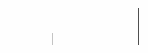
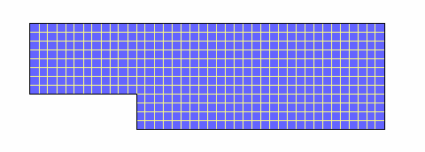
An example of a 2D analysis domain (flow over a backward facing step) and its mesh are shown in pictures below.
The process of obtaining an appropriate mesh (or grid) is termed mesh generation (or grid generation), and has long been considered a bottleneck in the analysis process due to the lack of a fully automatic mesh generation procedure. Specialized software progams have been developed for the purpose of mesh and grid generation, and access to a good software package and expertise in using this software are vital to the success of a modeling effort.
Mesh classification
As CFD has developed, better algorithms and more computational power has become available to CFD analysts, resulting in diverse solver techniques. One of the direct results of this development has been the expansion of available mesh elements and mesh connectivity (how cells are connected to one another). The elements in a mesh can be classified in various ways - the easiest is based upon the dimension and type of the elements. Common elements in 2D are triangles or rectangles, and common elements in 3D are tetrahedra or bricks. The most basic form of mesh classification is based upon the connectivity of the mesh: structured or unstructured.
Structured Meshes
A structured mesh is characterized by regular connectivity that can be expressed as a two or three dimensional array. This restricts the element choices to quadrilaterals in 2D or hexahedra in 3D. The above example mesh is a structured mesh, as we could store the mesh connectivity in a 40 by 12 array. The regularity of the connectivity allows us to conserve space since neighborhood relationships are defined by the storage arrangement. Additional classification can be made upon whether the mesh is conformal or not.
Unstructured Meshes
An unstructured mesh is characterized by irregular connectivity is not readily expressed as a two or three dimensional array in computer memory. This allows for any possible element that a solver might be able to use. Compared to structured meshes, the storage requirements for an unstructured mesh can be substantially larger since the neighborhood connectivity must be explicitly stored.
Hybrid Meshes
A hybrid mesh is a mesh that contains structured portions and unstructured portions. Note that this definition requires knowledge of how the mesh is stored (and used). There is disagreement as to the correct application of the terms "hybrid" and "mixed." The term "mixed" is usually applied to meshes that contain elements associated with structured meshes and elements associated with unstructured meshes (presumably stored in an unstructured fashion).
Algorithms
Since there are many different flow solvers with many different mesh requirements, there are also many different mesh generation algorithms. These are best classified in terms of the mesh that is generated: structured, unstructured, or hybrid.
Structured Algorithms
Many of the algorithms for the generation of structured meshes are descendents of "numerical grid generation" algoritms, in which a differential equation is solved to determine the nodal placement of the grid.
Elliptic Grid Generation
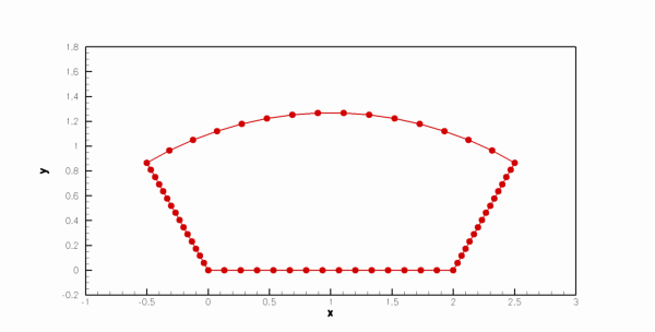
The oldest numerical grid generation techniques are based upon the solution of elliptic PDE's. Typically, a Poission-type equation is solved given the boundary grid distribution to generate interior nodal points. The solution domain is often topologically equivalent to a cube in 3D and a square in 2D. Consider the solution domain shown below with the indicated boundary resolution.
The simplest technique we could use here would be a solution of the Laplace equation using the standard second order finite difference stencil. This approach simplies into a form that is easily solved using Jacobi or Gauss-Seidel iterative techniques:
with Dirichlet boundary conditions is discretized as
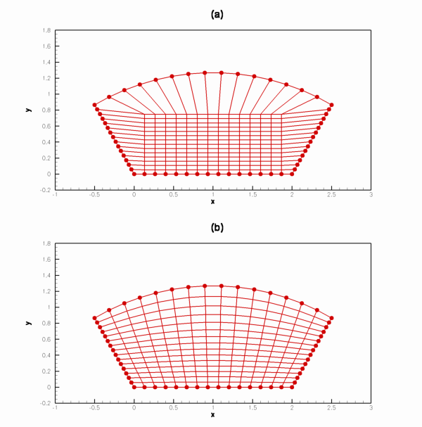
An initial grid is shown below in (a), and the resulting grid (after iterations) is shown in (b).
Note that the grid spacing near the curved section increases and then decreases as we move left to right. This is the primary reason that production grid generation techniques are usually more complicated. The addition of control functions allows for better grid clustering properties, which will be necessary for viscous flow simulations.


