NACA0012 airfoil
From CFD-Wiki
m (→Mesh) |
(→Lift Curve) |
||
| (13 intermediate revisions not shown) | |||
| Line 1: | Line 1: | ||
== Introduction == | == Introduction == | ||
| - | The NACA 0012 airfoil is widely used. The simple geometry and the large amount of wind tunnel data provide an excellent 2D validation case. For this case I use the Spalart-Allmaras turbulence model. | + | The NACA 0012 airfoil is widely used. The simple geometry and the large amount of wind tunnel data provide an excellent 2D validation case. For this case I use the [[Spalart-Allmaras model | Spalart-Allmaras]] turbulence model. |
<br> | <br> | ||
| + | |||
== Mesh == | == Mesh == | ||
[[Image:Naca0012 mesh final.JPG]] | [[Image:Naca0012 mesh final.JPG]] | ||
<br><br> | <br><br> | ||
| - | The mesh is a 30,000 cell C-grid. The width | + | The mesh is a 30,000 cell structured C-grid. The chord length is 1 m. The width of the first cell at the airfoil boundary is 0.02 mm. At Re = 3e6 and zero angle of attack, this results in a wall ''y+'' = 1.3 ± 0.4, which is low enough for the turbulence model to resolve the sub layer. The mesh shown is for an angle of attack of 6 degrees. |
<br> | <br> | ||
== Drag Coefficient == | == Drag Coefficient == | ||
| - | [[Image:Naca0012 cd | + | [[Image:Naca0012 cd tripwire2.JPG]] |
<br><br> | <br><br> | ||
| - | The drag coefficient at zero | + | The drag coefficient at zero angle of attack depends on the Reynold's number. The experimental data is for an airfoil with a trip wire, which forces the boundary layer to be completely turbulent.[1] This corresponds to the Fluent model, which has an active turbulence model over the complete airfoil. Note that the calculated drag coefficient is somewhat higher than the experimental one. Possibly, the modeled boundary layer is turbulent from the beginning, while in reality the trip wire is not at the very leading edge of the foil. |
<br> | <br> | ||
| - | Modeling the NACA 0012 airfoil without a trip wire is more complicated, since Fluent itself is unable to predict the point along the chord where the transition from a laminar to a turbulent boundary layer takes place. One option is to manually set this transition point at Re = | + | Modeling the NACA 0012 airfoil without a trip wire is more complicated, since Fluent itself is unable to predict the point along the chord where the transition from a laminar to a turbulent boundary layer takes place. One option is to manually set this transition point at Re = 5e5, which is the flat plate transition point.[2] |
<br> | <br> | ||
| + | |||
== Lift Curve == | == Lift Curve == | ||
| - | [[Image:Naca0012 lift | + | [[Image:Naca0012 lift curve3.JPG]] |
<br><br> | <br><br> | ||
| - | The lift coefficient depends on the angle of attack. For Re = 2e6 I compare the lift coefficient to experimental results.[ | + | The lift coefficient depends on the angle of attack. For Re = 2e6 I compare the lift coefficient to experimental results.[3] Because the lift coefficient is less sensitive to the transition point, the experimental data is for an airfoil without trip wire. (Later note: I have come to think that the presence of a stall angle has some element of luck. It turns out to be quite difficult to get one in Fluent.) |
<br> | <br> | ||
| Line 29: | Line 31: | ||
[[Image:Naca0012 lift curve slope.JPG]] | [[Image:Naca0012 lift curve slope.JPG]] | ||
<br><br> | <br><br> | ||
| - | The initial slope of the lift curve depends on the Reynold's number. Here I compare the lift curve slope to experimental results.[1] | + | The initial slope of the lift curve depends on the Reynold's number. Here I compare the lift curve slope to experimental results.[1] Experimental results are both with and without trip wire; again the lift coefficient is less sensetive to the transition point than the drag coefficient. |
<br> | <br> | ||
| + | |||
== References == | == References == | ||
1. W. J. McCroskey, ''A Critical Assessment of Wind Tunnel Results for the NACA 0012 Airfoil'', NASA Technical Memorandum 10001 9 (1987) <br> | 1. W. J. McCroskey, ''A Critical Assessment of Wind Tunnel Results for the NACA 0012 Airfoil'', NASA Technical Memorandum 10001 9 (1987) <br> | ||
| - | 2. L. Lazauskus, [ | + | 2. H. Slichting, K. Gersten, ''Boundary Layer Theory'', Springer-Verlag, Berlin/Heidelberg (2000), p. 33<br> |
| + | 3. L. Lazauskus, [http://www.cyberiad.net/library/airfoils/foildata/n0012cl.htm NACA 0012 Lift Data] | ||
Latest revision as of 08:54, 6 April 2010
Contents |
Introduction
The NACA 0012 airfoil is widely used. The simple geometry and the large amount of wind tunnel data provide an excellent 2D validation case. For this case I use the Spalart-Allmaras turbulence model.
Mesh

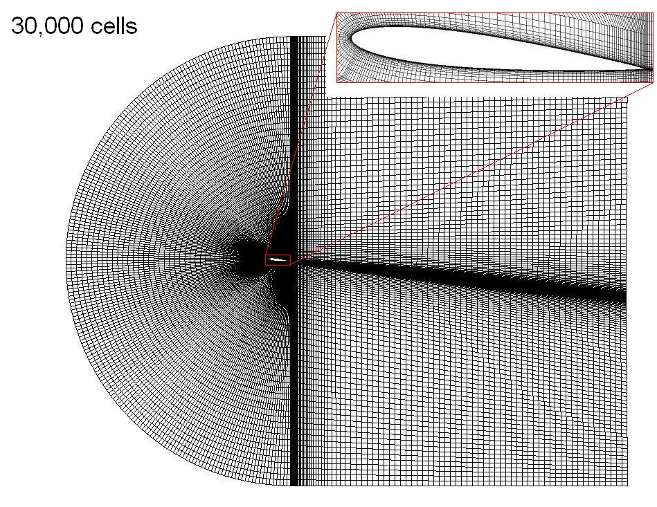
The mesh is a 30,000 cell structured C-grid. The chord length is 1 m. The width of the first cell at the airfoil boundary is 0.02 mm. At Re = 3e6 and zero angle of attack, this results in a wall y+ = 1.3 ± 0.4, which is low enough for the turbulence model to resolve the sub layer. The mesh shown is for an angle of attack of 6 degrees.
Drag Coefficient

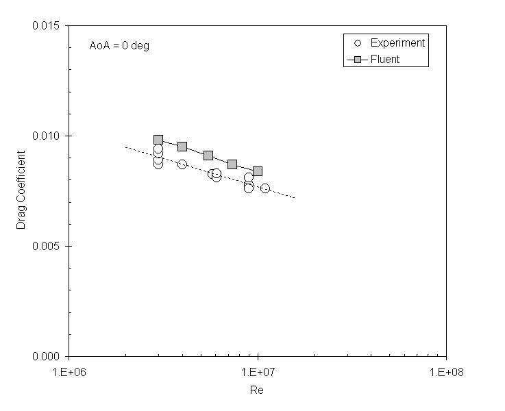
The drag coefficient at zero angle of attack depends on the Reynold's number. The experimental data is for an airfoil with a trip wire, which forces the boundary layer to be completely turbulent.[1] This corresponds to the Fluent model, which has an active turbulence model over the complete airfoil. Note that the calculated drag coefficient is somewhat higher than the experimental one. Possibly, the modeled boundary layer is turbulent from the beginning, while in reality the trip wire is not at the very leading edge of the foil.
Modeling the NACA 0012 airfoil without a trip wire is more complicated, since Fluent itself is unable to predict the point along the chord where the transition from a laminar to a turbulent boundary layer takes place. One option is to manually set this transition point at Re = 5e5, which is the flat plate transition point.[2]
Lift Curve

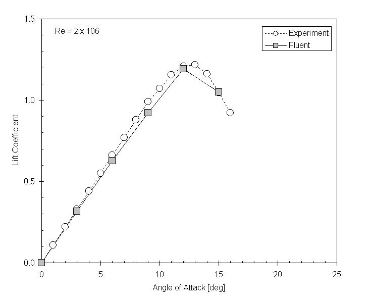
The lift coefficient depends on the angle of attack. For Re = 2e6 I compare the lift coefficient to experimental results.[3] Because the lift coefficient is less sensitive to the transition point, the experimental data is for an airfoil without trip wire. (Later note: I have come to think that the presence of a stall angle has some element of luck. It turns out to be quite difficult to get one in Fluent.)
Lift Curve Slope

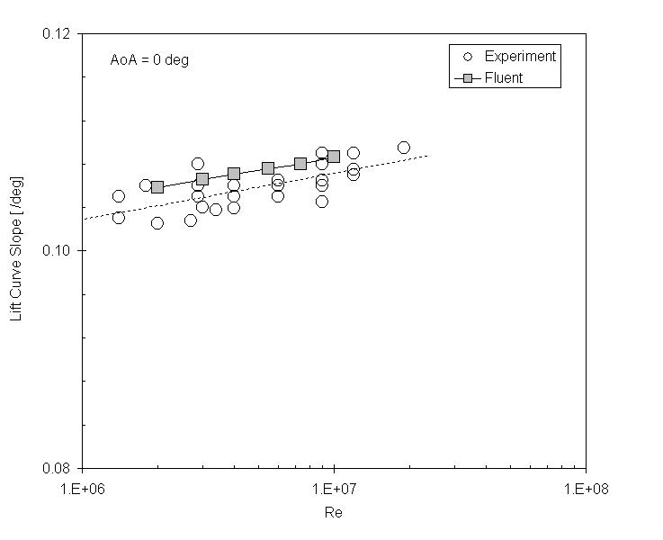
The initial slope of the lift curve depends on the Reynold's number. Here I compare the lift curve slope to experimental results.[1] Experimental results are both with and without trip wire; again the lift coefficient is less sensetive to the transition point than the drag coefficient.
References
1. W. J. McCroskey, A Critical Assessment of Wind Tunnel Results for the NACA 0012 Airfoil, NASA Technical Memorandum 10001 9 (1987)
2. H. Slichting, K. Gersten, Boundary Layer Theory, Springer-Verlag, Berlin/Heidelberg (2000), p. 33
3. L. Lazauskus, NACA 0012 Lift Data
